Kt 70 Installation Manual Jun 2026
Instead of decision trees, the manual uses numbered steps (e.g., “Check voltage at terminals 2-3. If no voltage, go to step 4…”). A true flowchart would be faster for intermittent problems.
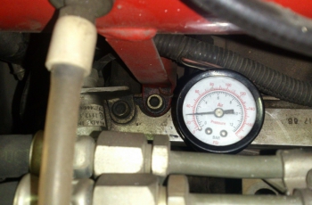
: This is a piece of industrial testing equipment used to generate and compare hydraulic pressure in a lab or on-site setting.
Use aerospace-grade wire for all power and ground connections (minimum 20 AWG).
The BendixKing KT 70 is a panel-mounted, Class 1A Mode S transponder designed to provide reliable air traffic control radar beacon system (ATCRBS) and Mode S capabilities. While it shares a physical footprint with older Mode A/C units like the KT 76A, its internal architecture and wiring requirements are significantly more complex.
Before signing off the installation logbook, execute the following tests using an approved avionics ramp test set (such as an IFR-6000 or equivalent): Kt 70 Installation Manual
Install the mounting tray (P/N 047-06368-0000) securely to the aircraft structure. It should be rigid to prevent vibration-induced damage. Clearance:
Connect the transponder to a dedicated circuit breaker ( Altitude Encoding: The
The external suppression line must be daisy-chained to other onboard pulse-transmitting avionics (such as DME or TCAS systems). This link blanks the transponder's receiver when other high-frequency equipment transmits, protecting internal circuitry from signal overload. Antenna Installation and RF Cabling
Is this for a or a replacement of an old transponder? What aircraft model are you installing this in? Will you be integrating it with a GPS for ADS-B compliance? Instead of decision trees, the manual uses numbered steps (e
Requires a standard L-band antenna (typically a whip or blade type). Altitude Source:
The KT 70 provides essential Mode S capabilities, including enhanced surveillance and Altitude Encoding. Unlike older Mode C transponders, the KT 70 offers:
This comprehensive guide breaks down the essential sections of the , detailing technical specifications, wiring configurations, and regulatory compliance requirements. 1. System Overview and Technical Specifications
: Traditional Gillham code connection requiring a multi-wire harness (A1, A2, A4, B1, B2, B4, C1, C2, C4, D4) routed from an encoding altimeter. : This is a piece of industrial testing
Mount the transponder antenna vertically on the bottom surface of the aircraft fuselage.
Shield the lighting and suppression lines to mitigate RF noise in the cockpit audio systems. Antenna Installation and Coaxial Cable Selection
The KT 70 must be connected to a gray code encoder for altitude reporting.
The following best practices should be followed during the installation of the KT 70 system:
Here is a structured, useful essay format outlining the key components for a KT 70 installation manual, designed for avionics technicians and installers. Installation Guide: KT 70 Mode S Transponder 1.0 Introduction and Scope
requires precise wiring for power, ground, and altitude encoding.